If you’ve ever stood next to a high-pressure plunger pump during operation—say, one powering a water jet cutter in a manufacturing shop, or a hydrostatic test skid at an oil and gas facility—you’ve probably heard a sharp, rhythmic whoosh that signals the pump is delivering fluid at thousands of pounds per square inch. What you might not hear, or even see, is the unassuming part that keeps the entire system from blowing apart: the relief valve. For anyone who’s relied on plunger pumps to move viscous fluids, power industrial processes, or withstand extreme pressure, the relief valve isn’t just a secondary component—it’s the quiet guardian of uptime, safety, and equipment longevity. As a plunger pump supplier who’s worked with clients ranging from small fabricators to large petrochemical operators over the last 12 years, I’ve lost count of how many project kickoff calls start with, “We installed a cheap pump last quarter and the relief valve failed—now we’re down $50,000 in parts and time.” That reality is what makes today’s topic so critical: let’s break down exactly what a relief valve does in a plunger pump, why cutting corners on this part is one of the costliest mistakes you can make, and how to pair the right relief valve with your pump for long-term success. Plunger Pump
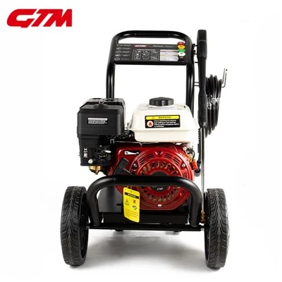
First, let’s ground this in how a plunger pump works, because the relief valve’s role only makes sense when you understand the pump’s core function. Unlike centrifugal pumps, which move fluid by spinning an impeller to create continuous flow, plunger pumps are positive displacement devices. That means a reciprocating plunger (think of a thick, sturdy rod) slides back and forth inside a sealed cylinder. On the forward stroke, fluid is drawn into the cylinder through an inlet valve, then trapped on the reverse stroke as the inlet closes and a discharge valve opens to push pressurized fluid out. The key here is positive displacement: every full cycle of the plunger moves a fixed, precise volume of fluid, regardless of downstream pressure. So if there’s nowhere for that fluid to go—say, a closed valve in the line, or a blocked filter downstream—the pressure inside the pump’s cylinder and piping will spike exponentially. Plunger pumps are built to handle extreme pressure, but even the most robust unit can only withstand so much. Run that pressure too high, and you’ll face a chain reaction: cracked cylinder heads, sheared plunger rods, ruptured high-pressure hoses, or even catastrophic line failures that send fluid and debris flying. That’s exactly where the relief valve steps in.
At its most basic, the relief valve’s job is to control and limit maximum system pressure by providing a safe, controlled path for excess fluid to escape before pressure reaches dangerous levels. But it’s not a one-size-fits-all component. Plunger pump relief valves come in a few main types, each tailored to different applications, and their placement on the system is just as important as their design. For example, direct-acting relief valves are the most common for smaller, lower-pressure plunger pumps (think 10,000 PSI or less) used in cleaning, water jet cutting, or light industrial applications. These valves work simply: when system pressure exceeds the valve’s pre-set limit, a spring-loaded poppet opens to bleed excess fluid back to the pump’s suction line or a dedicated return tank. They’re responsive, affordable, and easy to adjust on-site, which makes them popular for operators who need to tweak pressure for different jobs. For higher-pressure plunger pumps—say, 20,000 PSI and up used in oil and gas well testing, subsea equipment, or heavy hydrostatic applications—pilot-operated relief valves are the go-to. These use a small, separate pilot valve to control the main valve’s opening, which means they can handle far higher flow rates and pressure spikes without the wear and tear that would destroy a direct-acting valve over time. I’ve seen this play out firsthand: a client of ours a few years ago was using a direct-acting valve on a 15,000 PSI plunger pump for a pipeline pressure test. After three weeks of continuous operation, the valve’s spring wore out from constant opening and closing, leading to a 2,000 PSI spike that cracked the pump’s cylinder. Swapping to a pilot-operated valve fixed that, and the pump ran without issues for another two years on the same project.
But the relief valve does more than just prevent catastrophic failure. It also plays a key role in process stability and pump longevity. Let’s circle back to positive displacement: because plunger pumps push a fixed volume of fluid, any restriction in the discharge line causes pressure to rise, which means the pump has to work harder to move that fluid. Over time, that constant high load on the plunger, valves, and drive motor will shorten the pump’s lifespan—think of a runner forcing a closed fist through a narrow pipe, straining their arm every time. A properly sized relief valve bleeds off that excess volume before pressure spikes, taking the load off the pump’s internal components. I always tell new clients: a plunger pump’s failure rarely happens because the pump is bad—it happens because the system around it is poorly designed, and the relief valve is the most critical part of that system. For example, a client in the food and beverage industry reached out to us last year, saying their batch cleaning plunger pumps were failing every 6 months, while a competitor’s pump on a similar line had run for 3 years without issues. We dug into their setup, and found they were using an off-the-shelf relief valve pre-set to 1,000 PSI, but their batch process required varying pressure between 800 and 1,200 PSI. The valve was constantly opening and closing 10 times per minute to compensate for pressure fluctuations, causing premature wear on the valve’s poppet and seal. By swapping to a proportional relief valve that adjusts pressure gradually instead of on-off, we cut pump failure rate by 90% and extended valve life by 18 months. That’s the kind of detail that makes a difference for operators, not just big numbers on a spec sheet.
Another often-overlooked role of the relief valve is over-speed protection, especially in plunger pumps powered by variable speed drives (VSDs) or diesel engines. If a pump’s drive motor or engine speeds up unexpectedly—say, a voltage spike from the power grid, or a faulty speed controller—the plunger will cycle faster, moving more fluid per minute, which causes pressure to rise even if the discharge line is open. The relief valve acts as a last line of defense here, bleeding off excess flow before pressure spikes. I remember a case a few years back where a remote plunger pump at a mining site had its speed controller fail, ramping the pump to twice its intended speed. The relief valve opened immediately, preventing a line rupture that would have forced a 72-hour shutdown to repair—critical for a mine operating on a tight production schedule. That’s the value of a relief valve that’s matched to the pump’s maximum flow, not just its maximum pressure rating.
But here’s the catch: not all relief valves are created equal, and choosing the wrong one can do more harm than good. For example, many operators try to save money by using a relief valve sized for a lower-pressure pump, or a general-purpose valve meant for centrifugal pumps, on their plunger pump. Centrifugal pumps don’t have positive displacement, so their relief valves are designed to handle different pressure dynamics. Plunger pumps experience rapid pressure spikes (called pressure “water hammer”) every time the discharge valve opens or closes, which means a relief valve for a centrifugal pump will either open too slowly to stop the spike, or wear out quickly from the repetitive force. Another common mistake is setting the relief valve’s pressure too high. Operators often do this to “get more out of the pump,” but that just adds unnecessary strain on the plunger, seals, and drive motor, leading to higher maintenance costs and shorter pump life. I always recommend setting the relief valve 10-15% above the pump’s maximum operating pressure, not higher, to balance process needs and equipment longevity.
As a plunger pump supplier, part of my job isn’t just to sell pumps—it’s to make sure our clients have the right support components to keep those pumps running reliably. That’s why we work with every client to not only select the right plunger pump for their application, but also help them size and set up their relief valve correctly. Last year, we paired a high-pressure plunger pump with a pilot-operated relief valve for a geothermal well testing project. The project required consistent pressure between 5,000 and 10,000 PSI, with frequent adjustments as they drilled deeper. We worked with the site engineer to set the valve’s maximum pressure at 11,500 PSI (the 15% buffer we recommend), and installed a pressure gauge next to the valve so operators could adjust it safely without guesswork. The project ran for 6 weeks straight with no downtime, which saved the client well over $100,000 in potential lost production from unexpected failures. That’s the kind of impact getting the relief valve right has.
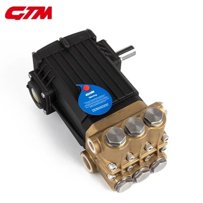
Now, if you’re working with plunger pumps, whether you’re a plant manager, a maintenance technician, or a project engineer, I don’t need to tell you how expensive downtime can be. A single hour of unplanned shutdown on a high-pressure plunger pump can cost tens of thousands of dollars in lost production, not to mention repair costs. The relief valve is one of the only components that directly prevents that, and it’s often the most underrated part of the whole system. If you’re currently experiencing pump failures, or you’re planning a new project and want to make sure your setup is built to last, I’d encourage you to reach out to talk through your needs. We’ve worked with thousands of clients across industries, from small machine shops to large energy companies, and we can help you select the right relief valve (and matching plunger pump) for your specific application, no matter how high-pressure or specialized it is. Don’t wait for a failure to invest in the component that keeps your system safe and running.
High Pressure Nozzle References:
- Garay, L. (2012). Positive Displacement Pump Handbook (2nd ed.). Elsevier.
- Heald, R. (2018). Hydraulic Control Systems: Design and Analysis (3rd ed.). John Wiley & Sons.
- American Petroleum Institute. (2020). API Standard 675: Positive Displacement Pumps—Centrifugal and Rotary Pumps. API Publishing Services.
Zhejiang GTM Hi-Tech Intelligent Equipment Co., Ltd.
As one of the most professional plunger pump manufacturers and suppliers in China, we also support customized service. With abundant experience, we warmly welcome you to buy discount plunger pump for sale here from our factory. For price consultation, contact us.
Address: No.5 of Changjiang Road, 2nd Economic Development Zone of Wenling, Zhejiang, China
E-mail: yehuanting1@hongyemfg.com
WebSite: https://www.gtm-plungerpump.com/
